
Motion Transmission Systems
Motion transmission systems maintain the same type of motion between the driver and the driven components.
Motion transmission is a complex mechanical function, because it is performed by a mechanism, which is a set of components. The same type of motion is transmitted from one component to another. Therefore, the rotational motion of the driver component (or driving unit) drives the rotational motion of the driven component (or receiving unit).
There are five motion transmission systems.
| System Name (Click on the links below) |
Operation | Reversibility |
|---|---|---|
Friction gear systems |
The rotational motion of the driver gear drives the rotational motion of the driven gear due to the friction between them. | Reversible |
Belt and pulley systems |
The rotational motion of the driver pulley drives the rotational motion of the driven pulley using the belt as the intermediate component. | Reversible |
Gear trains |
The rotational motion of the driver gear drives the rotational motion of the driven gear when the teeth of the driver gear push on the teeth of the driven gear. | Reversible |
Chain and sprocket systems |
The rotational motion of the driver sprocket drives the rotational motion of the driven sprocket using the chain as the intermediate component. | Reversible |
Worm and worm gear systems |
The rotational motion of the worm drives the rotational motion of the worm gear when the threads of the worm push on the teeth of the worm gear. | Irreversible |
Friction Gear Systems
Friction gear systems transmit rotational motion due to friction between two or more gears.

Fiction gear system symbol
The gears have to touch for the motion to be transmitted.
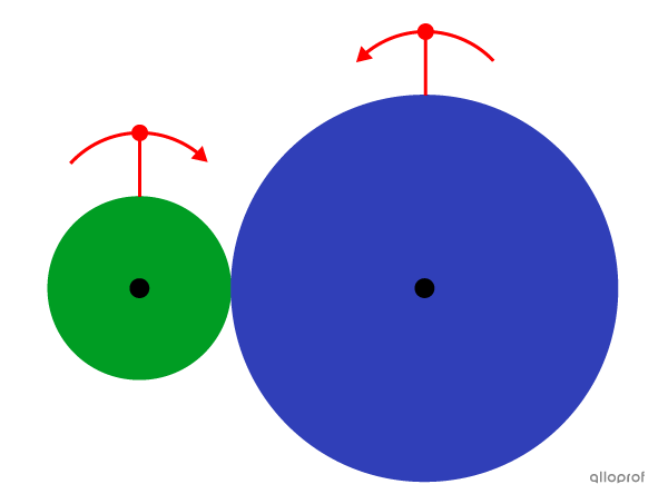
A friction gear system
Friction gears can be positioned perpendicularly, allowing rotational motion along different axes.
In this image, the rotational motion of the driver gear (along a vertical axis) drives the rotational motion of the driven gear (along a horizontal axis).
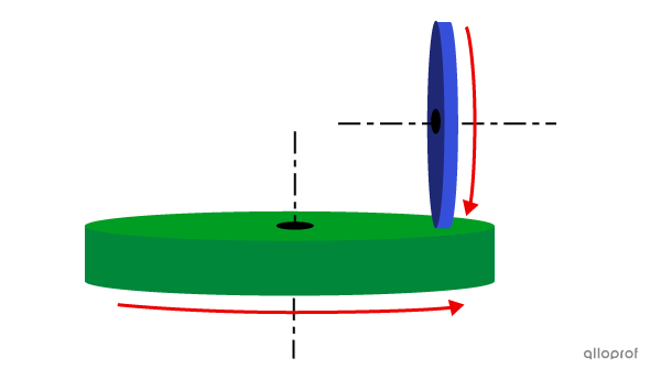
Perpendicular friction gears
Some bicycles are equipped with a dynamo, a device that generates electricity and powers a headlight on the bicycle.
The dynamo has a small wheel which is in contact with one of the bicycle wheels. The rotational motion of the bicycle wheel (driver) drives the rotational motion of the dynamo wheel (driven).
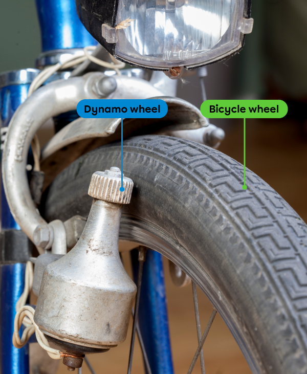
Bicycle dynamo
Adapted from OKcamera, Shutterstock.com
Motion Characteristics (Secondary 3)
Click the following links to know more about each characteristic.
Friction gear systems are reversible, because either gear can be the driver or the driven component.
Direction of rotation of components
The direction of rotation of the driver gear is identical to the driven gear when the system contains an odd number of friction gears.
The direction of rotation of the driver gear is opposite to the driven gear when the system contains an even number of friction gears.
Friction gear systems allow speed changes when the diameters of the driver and the driven gears are different.
Advantages and Disadvantages (Secondary 4)
| Advantages | Disadvantages |
|---|---|
|
|
Belt and Pulley Systems
The belt and pulley system transmits rotational motion between two or more pulleys spaced apart from each other. A belt (an intermediate component) transmits the motion.

Belt and pulley system symbol
The belt and pulley system consists of a belt and two or more pulleys. Each pulley touches the belt.
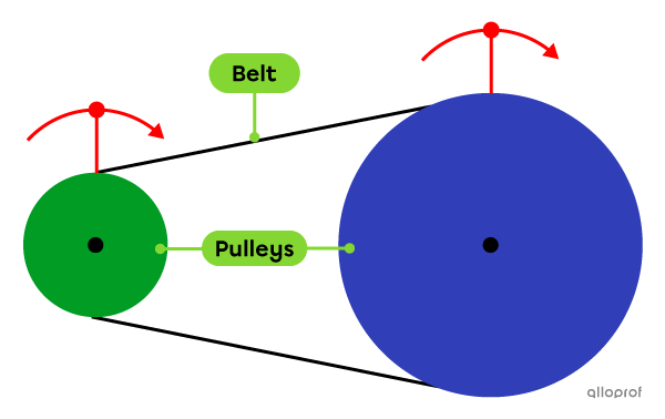
The belt and pulley system
To prevent the belt from slipping off the pulleys and ensuring efficient motion transmission, sufficient adhesion is required between the pulleys and the belt. It is important to remember when choosing materials.
To increase the adhesion between the belt and the pulleys, certain parameters are customizable, such as the tension of the belt and the type of belt and/or pulleys.
It is possible to increase the adhesion of the belt by using a timing belt, which has teeth, or notches, and is usually made of rubber.
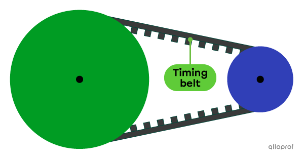
A timing belt and pulley system
A scooter’s transmission is a timing belt and pulley system. The system transmits the rotational motion generated by the motor to the rear wheel of the scooter.
The rotational motion of the variator pulley drives the rotational motion of the clutch pulley using a timing belt.
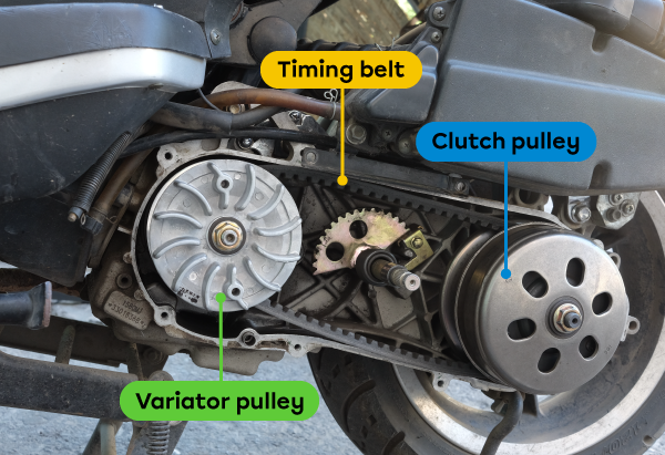
A scooter transmission
Adapted from Aleksandr Shilov, Shutterstock.com
Due to the flexibility of the belt, different configurations are possible.
-
The belt can be crossed, changing the direction of rotation of the driven pulley.
-
The pulleys can be positioned perpendicularly to each other, allowing rotational motion along different axes.
In this image, the rotation of the driver pulley (along a vertical axis) drives the rotation of the driven pulley (along a horizontal axis).
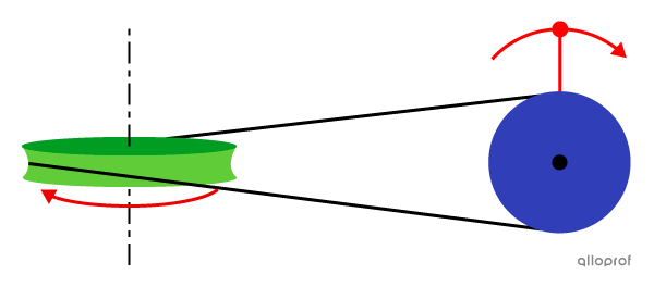
A belt and pulley system with different rotational axes
This old lawn mower works with a belt and pulley system. The pulleys are driven along different axes.
The rotational motion of the motor pulley (along a horizontal axis) drives the rotational motion of the blade pulley (along a vertical axis) using the belt.
The blade is attached to the blade pulley. Therefore, the blade is driven in a rotational motion to cut grass.
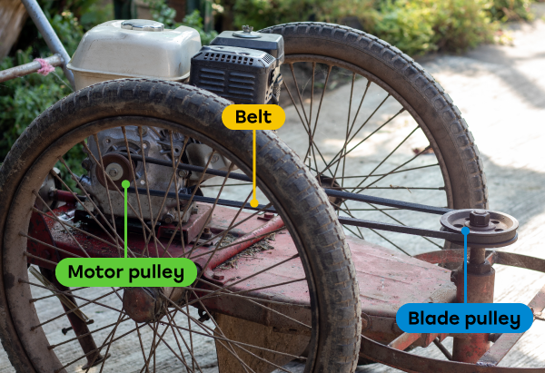
An old lawn mower
Adapted from Itthiphon_No, Shutterstock.com
Motion Characteristics (Secondary 3)
Click the following links to know more about each characteristic.
Belt and pulley systems are reversible, because both pulleys can be the driver or the driven component.
Direction of rotation of components
The direction of rotation of the pulleys positioned on the same side of the belt is identical.
The direction of rotation of the pulleys positioned inside the belt is opposite to the ones positioned outside the belt.
When the belt is crossed, the direction of rotation of the pulleys is switched.
Belt and pulley systems allow speed changes when the diameters of the driver and the driven pulleys are different.
Advantages and Disadvantages (Secondary 4)
| Advantages | Disadvantages |
|---|---|
|
|
Gear Trains (or Gear Assembly)
Gear trains, or gear assembly, transmits rotational motion between two or more wheel gears due to their interlocking teeth.

Gear trains (or gear assembly) symbol
The gear train consists of at least two wheel gears with interlocking teeth. When the driver gear rotates, its teeth come into contact with the driven gear’s teeth, one after another. In other words, they mesh together. Every tooth on the driver gear pushes on a tooth on the driven gear.
Therefore, the rotational motion of the driver gear drives the rotational motion of the driven gear.
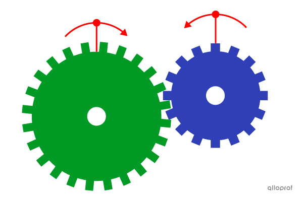
Gear trains
In a mechanical watch, gear trains enable the rotation of the hour hand, the minute hand, and the second hand. The gears transmit rotational motion to different watch components.
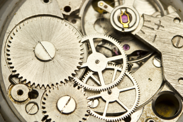
Mechanical watch mechanism
Fedorov Ivan Sergeevich, Shutterstock.com
Wheel gears can be positioned perpendicularly to each other, enabling rotation along different axes. For them to mesh well, they have to have a conical shape. They are called bevel gears.
In this image, the rotational motion of the driver gear (along a vertical axis) drives the rotational motion of the driven gear (along a horizontal axis).
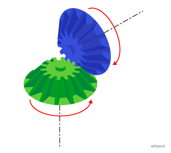
Bevel gears
To increase stability when making turns, cars are equipped with a differential.
The differential consists of several bevel gears transmitting motion by changing the axis of rotation from one component to another.
During a turn, the gears transmit rotational motion to the wheels of the car while adapting the speed of each wheel.
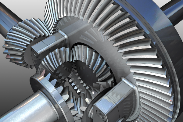
A car differential
Nikonaft, Shutterstock.com
Motion Characteristics (Secondary 3)
Click the following links to know more about each characteristic.
Gear trains are reversible, because both wheel gears can be the driver or the driven component.
Direction of rotation of components
The direction of rotation of the driver gear is identical to the driven gear when the system contains an odd number of wheel gears.
The direction of rotation of the driver gear is opposite to the driven gear when the system contains an even number of wheel gears.
Gear trains allow speed changes when the diameters of the driver and the driven gears are different.
Advantages and Disadvantages (Secondary 4)
| Advantages | Disadvantages |
|---|---|
|
|
Chain and Sprocket Systems
Chain and sprocket systems transmit rotational motion between sprockets spaced apart from each other. A chain (an intermediate component) transmits the motion.

Chain and sprocket system symbol
The chain and sprocket system consists of a chain and at least two sprockets. Each sprocket engages the chain, the teeth meshing with the chain links.
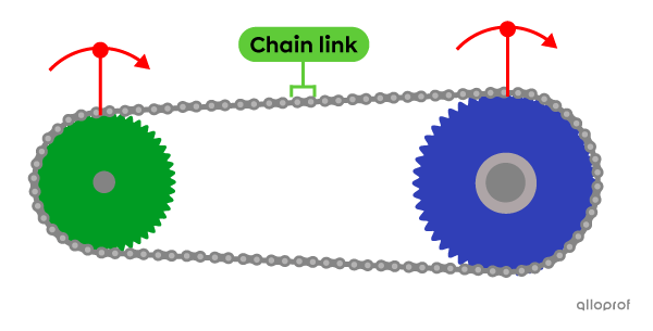
A chain and sprocket system
A bicycle uses a chain and sprocket system. The rotational motion of the crankset drives the rotational motion of the rear sprocket using the chain.
The rear sprocket is attached to the rear wheel and its rotational motion moves the bike forward.
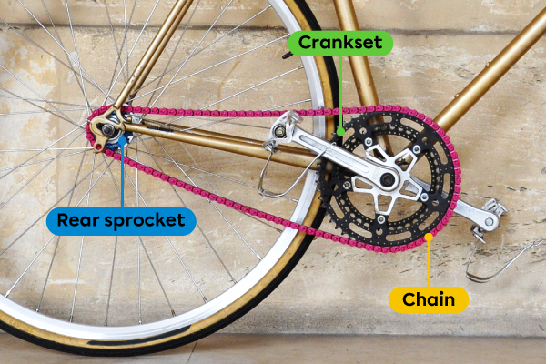
A chain and sprocket system in a bicycle
Adapted from Thomas Dutour, Shutterstock.com
Motion Characteristics (Secondary 3)
Click the following links to know more about each characteristic.
Chain and sprocket systems are reversible, because both sprockets can be the driver or the driven component.
Direction of rotation of components
The direction of rotation of the sprockets positioned inside the chain is identical.
The direction of rotation of the sprockets positioned outside the chain is identical.
The direction of rotation of the sprockets positioned inside the chain is opposite to those positioned outside the chain.
Chain and sprocket systems enable speed changes when the diameters of the driver and the driven sprockets are different.
Advantages and Disadvantages (Secondary 4)
| Advantages | Disadvantages |
|---|---|
|
|
Worm and Worm Gear Systems
The worm and worm gear systems transmit rotational motion from the worm (or screw gear) to the worm gear (or wheel gear).

The worm and worm gear system symbol
The worm and worm gear system consists of a single threaded worm in contact with one or multiple worm gears.
As the worm rotates, its threads mesh with the teeth of the worm gear, driving its rotational motion.
One complete rotation of the worm rotates the worm gear by one tooth. This system allows for a great decrease of speed.
The worm can drive the rotation of the worm gear indefinitely.

A worm and worm gear system
Guitar tuning pegs use the worm and worm gear system.
The rotational motion of the worm drives the rotational motion of the worm gear. Each worm gear is attached to a guitar string for tightening when needed.
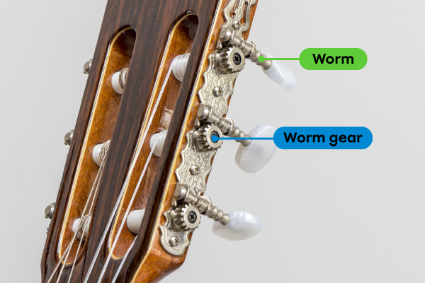
Guitar tuning pegs
Adapted from Dan Bridge, Shutterstock.com
Motion Characteristics (Secondary 3)
Click the following links to know more about each characteristic.
The worm and worm gear system is irreversible, because only the worm (driver component) can activate the mechanism. The worm gear is locked and cannot initiate the motion.
Direction of rotation of components
The direction of rotation of components cannot be compared, because the axis of rotation of the worm is perpendicular to the axis of rotation of the worm gear.
The worm gear system decreases the speed of rotation transmitted to the worm gear.
Advantages and Disadvantages (Secondary 4)
| Advantages | Disadvantages |
|---|---|
|
|
Exercises
- Top of page
- Friction Gear Systems
- Motion Characteristics (Secondary 3)
- Advantages and Disadvantages (Secondary 4)
- Belt and Pulley Systems
- Examples
- Motion Characteristics (Secondary 3)
- Advantages and Disadvantages (Secondary 4)
- Gear Trains (or Gear Assembly)
- Motion Characteristics (Secondary 3)
- Advantages and Disadvantages (Secondary 4)
- Chain and Sprocket Systems
- Motion Characteristics (Secondary 3)
- Advantages and Disadvantages (Secondary 4)
- Worm and Worm Gear Systems
- Motion Characteristics (Secondary 3)
- Advantages and Disadvantages (Secondary 4)
- Exercises
- See Also
